

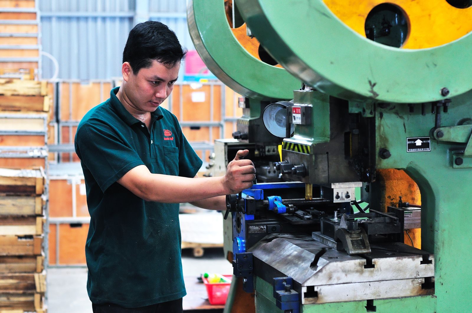
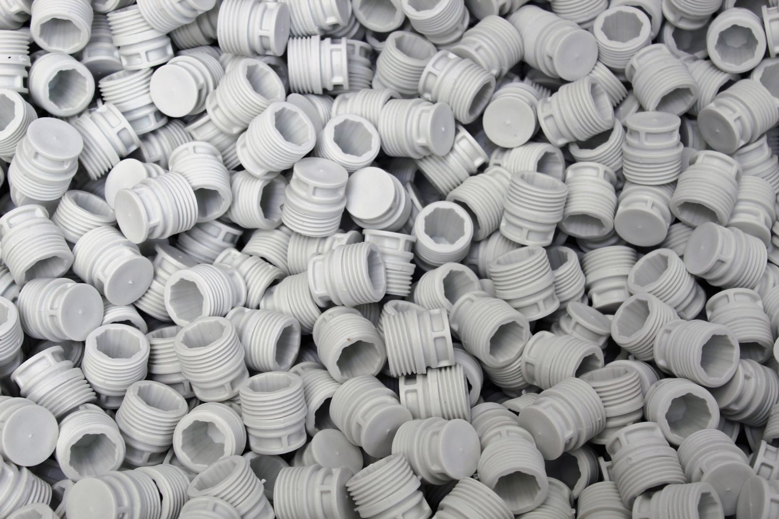
Walk along a modern production line and a large share of what you see is not steel. Guards, sensor brackets, terminal covers, handles, cable ducts, control housings, and wear pads are increasingly molded components, and the reasons are practical rather than fashionable.
Four benefits drive the substitution. Electrical insulation comes free with the material choice, which removes separate insulating parts from the assembly. Corrosion resistance removes plating, painting, and the touch-up work that follows. Complex geometry costs little extra once the tool is cut, because the shape comes from the mold rather than from machining time. And weight falls, which matters on anything an operator lifts or a machine has to accelerate.
The trade-off is structural. Molded plastic is not a substitute for steel in load-bearing frames, and it is a poor choice where impact, sustained heat, or repeated high stress is normal. A part that keeps cracking in service usually needs a different material family, a thicker section, or a design change rather than a different supplier.
Material selection does more to determine whether a part succeeds than any other single decision, and it is the decision most often made by habit. The families below cover most machine components.
| Material | Typical use on machinery | What to design around |
|---|---|---|
| ABS | Housings, covers, and enclosures where appearance matters | Moderate chemical resistance; unprotected outdoor exposure degrades and chalks |
| Polyamide (nylon), often glass-filled | Brackets, clips, small structural parts, and gears | Absorbs moisture, so dimensions move; conditioning matters before precision use |
| Polycarbonate | Guards and windows that have to resist impact | Sensitive to some solvents and to stress cracking at molded-in stress |
| POM (acetal) | Bushings, rollers, and sliding wear parts | Poor surface for bonding and printing; needs mechanical fastening features |
| Polypropylene | Tanks, ducts, and parts exposed to wash-down chemicals | Low stiffness; not for tight-tolerance or load-bearing duty |
| TPE / TPU | Grips, seals, and over-molded soft surfaces | Only bonds to compatible substrates; over-molding adds tooling work |
Two questions narrow the list faster than any data sheet. What temperature does the part see in normal operation and during cleaning, and which chemicals or lubricants will it contact? A part specified from a data sheet alone, without knowing the cleaning agents used on the line, is a part that gets re-ordered in a different material within a year.
Moldability is a property of the design, not something a molder adds afterwards. Wall thickness should be as uniform as function allows, because thick sections cool more slowly, pull harder, and leave sink marks on the visible face. Ribs stiffen a part without adding thickness; a workable starting point is a rib thickness of roughly half to two-thirds of the adjoining wall, tapering toward the tip and drafted on both sides. Bosses for screws or inserts need a wall around a hole rather than a solid mass of plastic, and they should be tied to the nearest wall with a rib instead of standing alone.
Draft is what lets the part leave the tool. Every vertical face needs it, including the sides of ribs and bosses, and text or texture on a wall increases the draft that wall requires. Sharp inside corners concentrate stress and restrict flow; a radius costs nothing in tooling terms and removes a common crack initiation point.
Gate location is the third decision that reaches into performance. Where the plastic enters the cavity sets the weld lines, the flow direction, and how much the part warps. Glass fibres align with the flow, so a gate placed for convenience can leave a part that is strong in one direction and weak in the other. If the part carries a load, gate position belongs in the design review rather than in the molder's discretion.
Injection molding has a high fixed cost and a low variable cost. The tool is the fixed cost; the part price follows cycle time and shot weight. That shape means the process wins when annual volume is high enough to spread the tool across many parts, and loses when volume is small or the design is still moving.
| Situation | Usually the better route |
|---|---|
| High annual volume, stable design, complex geometry | Injection molding |
| Low volume, urgent need, no budget for a tool | Machining from stock |
| Large flat panels and simple brackets | Sheet metal, unless insulation or corrosion pushes toward plastic |
| A design that is still changing every quarter | Machining or additive manufacturing until the geometry freezes |
| A family of similar parts in different colours | Molding, if the parts can share a tool and a material |
A useful discipline is to freeze the design before committing to a tool. Changes after the tool is cut are paid for twice, once in tool modification and once in lost time, and the lost time is usually the larger cost.
Send the 3D model in a neutral format, a 2D drawing with the tolerances that actually matter to function, the material or the performance the material has to meet, the annual volume and expected program life, and the environment the part will live in. Say which dimensions are functional and which are cosmetic. A molder who knows that one hole position is critical and the rest of the part is a cover will quote differently, and more usefully, than one who is asked only to price a model.
Get the tooling assumptions in writing: number of cavities, expected tool life, who owns the tool, and what a design change costs after first article. Those four answers separate quotes that differ for good reasons from quotes that were never comparable.
It also helps to choose a supplier whose normal work is engineering-grade parts rather than commodity packaging. Material and tooling decisions of the kind described above are the routine business of a specialist plastic injection molding manufacturer, and involving one while the geometry can still change costs far less than discovering the problem after the tool is cut.
Start with the function rather than the material. If the part insulates, isolates, covers, guides, or carries a light load in a corrosive environment, plastic is worth designing around. If it carries structural load, absorbs impact, or runs hot, metal usually wins and a plastic design will keep coming back for revision.
There is no universal threshold, because it depends on what the part costs to make by the alternative route and how long the program will run. The honest calculation compares tool cost plus molded part price against the alternative process over the expected program life, including the design changes you already know are coming.
Often, where the shrinkage of the new material is close to the old one and the processing temperatures are compatible. Where shrinkage differs significantly the tool can sometimes be re-cut, but the safe assumption is that a late material change means tool work.
At ZH Industrial Machinery, machine design, guarding, and component detail are worked through together, because those choices set the tooling and the maintenance access for the life of the machine. If you are specifying parts for a new build or replacing a component that keeps failing, send us the application and we will recommend a material and a manufacturing route.
The process constraints described here - draft, wall uniformity, shrinkage and flow orientation - are the general discipline of injection moulding. The material and test nomenclature a specification leans on comes from ASTM International, and the traceability of any dimensional measurement rests on NIST.